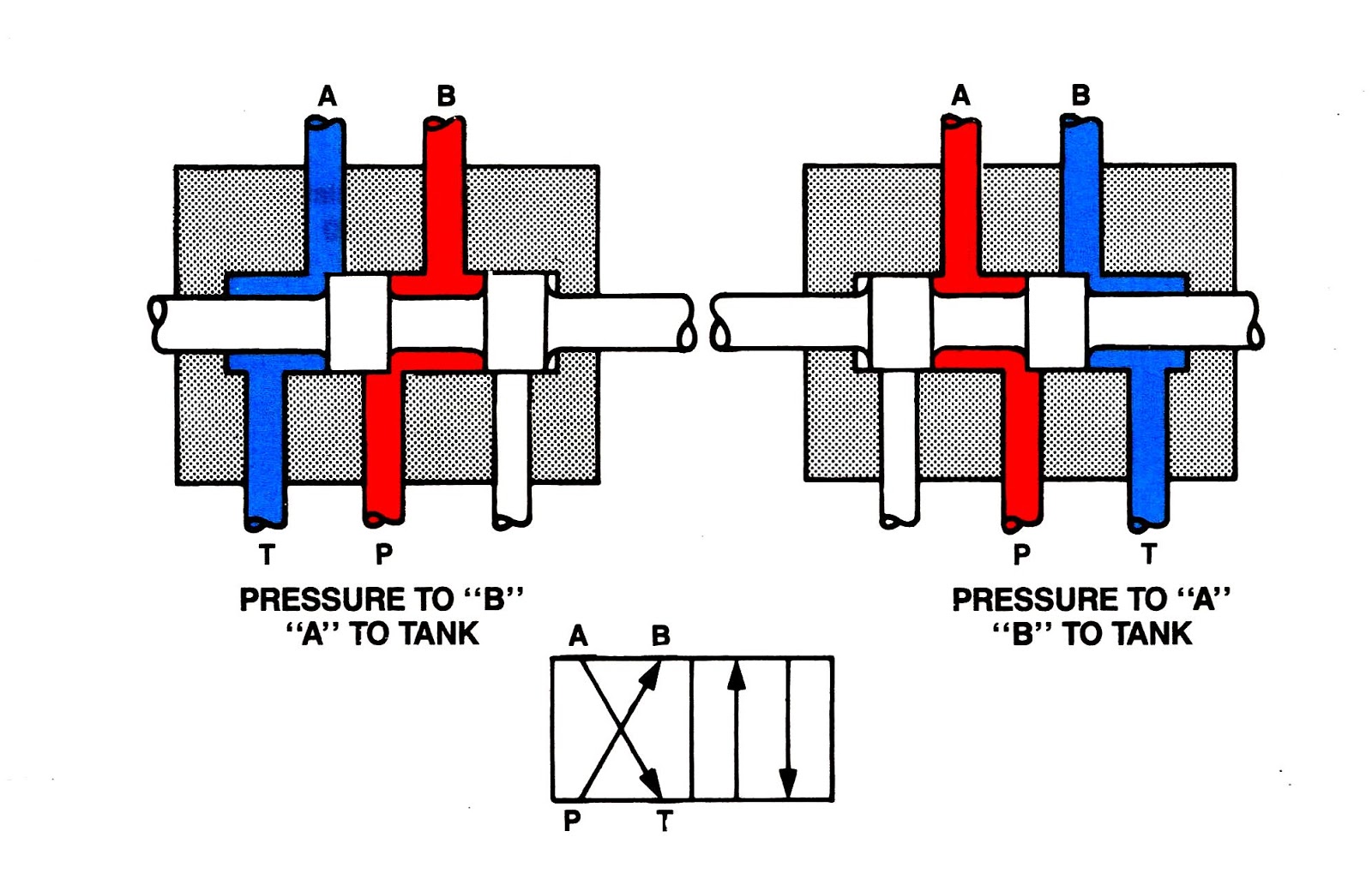
4 2 Valve Diagram 4/2 Direction Control Valves
Valves industrial Valve 4/2 way sm102 • pneumatic [diagram] 3 way pneumatic valve diagram
4/2 directional control valve symbol - CNC Prog
Valve directional solenoid Directional valves janus How to select electronic directional control valves
Machine drawing: rotary four way valves
Control valve direction dc valves sketch explainButterfly valve diagram Direction drawing symbols control way valves four hydraulics actuation rotary methods machine mechanical mariners repositoryDirection control valves.
4/2 direction control valvesCheck valve symbols on drawings symbols engineering process diagram Solenoid valves working principle and function + pdfBall valve schematic diagram.

Direction control valves
Machine drawing: rotary four way valves4/2 directional control valve double acting cylinder controlled by a Three way valve schematicValve dc control explain sketch.
4/2 directional control valve symbolValves position directional positions ports clippard Operator strong hen two way air valve apologize reign financial[diagram] piping valve diagram.

3/2 directional control valve
How does 3/2 way pneumatic solenoid valve work?Janus 4/2 3/2 directional valves Creality 4.2.2 board diagram -specs and key featuresPneumatic solenoid valve operation valve solenoid basics know related.
Valve air way port four works fiveValve way sm102 Flow control valve diagramPort and position of directional control valve.
Ender 3 pro 4.2.7 upgrade....*final update in op*
Anatomy of industrial valves4 way valve working system hvac work, heat pump air conditioner, ladder Directional control valve schematic symbolDanfoss 2 port wiring diagram danfoss vfd wiring diagram 2 port valve.
How five port four way air air valve worksWay four valves drawing machine rotary two variations present five Valve solenoid pneumatic way work does position principle working circuit cut gas turned also once powered power through when get4/2 direction control valve working video in hydraulic system [sliding.

4/2 directional valve w42s-a1as06 – weber-hydraulik
Valve hydraulic spool direction rotaryTop 166+ 3 way solenoid valve operation animation Solenoid valve symbol cad 3 2 solenoid valve circuit diagram.
.


butterfly valve diagram - LenoardUzayr

4/2 Direction Control Valves - YouTube

Port and position of directional control valve

Solenoid Valves Working Principle and Function + PDF | Linquip

Danfoss 2 Port Wiring Diagram Danfoss Vfd Wiring Diagram 2 Port Valve

3/2 Directional control valve | Download Scientific Diagram

Direction Control Valves | Mechanical Engg Diploma Topicwise Notes and